3D House Number Backlit Letter Installation Instructions
you can download a printable version of installation instructions from here
Illustrations:
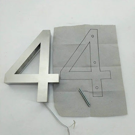
Backlit number, screws, and installation template:
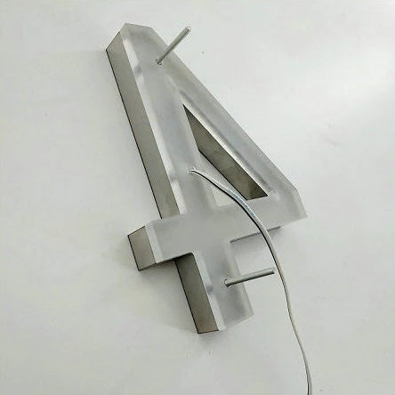
Back of the backlit number showing screwed screws:
50W+ LED Driver - 110V AC to 12V DC Converter Transformer:
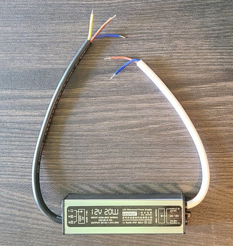
** We will include the correct size transformer needed for your numbers based on our power calculations.
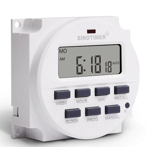
Timer - Auto On/Off:
Dusk to Dawn Sensor - Auto On/Off:

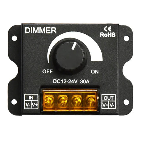
Dimmer:
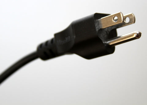
Plug - To connect to Outlet:
Solar Panel Power Bank:

Powering options:

What do you need for installation:
- Backlit address numbers - included
- LED Driver - 110V AC to 12V DC converter transformer - included if purchased
- Installation template - included
- Mounting screws - included
- 16AWG wire – not included
- (Optional) Plug - included if purchased
- (Optional) Timer Auto On/Off - if purchased
- (Optional) Dusk to Dawn Light Auto On/Off - if purchased
- (Optional) Dimmer - if purchased
- Painters tape - not included
- Drill - not included
- 5/32" drill bit - not included
- Level - not included
- Exterior grade epoxy - not included
Mounting instructions:

Installation instructions for the 50W or higher LED driver option:
- Before you start the installation process, please read our caution at the bottom of this page.
- Tape the included installation template to the wall and drill holes for the screws and the wires at the designated marks on the template using a 5/32" drill bit.
- Screw the screws into the holes on the back of the backlit numbers.
- Add some epoxy to the other end of the screws at the back of the backlit numbers.
- Remove the installation template and mount the backlit numbers on the wall by aligning the screws to the holes you drilled in the wall and pushing the screws into the holes.
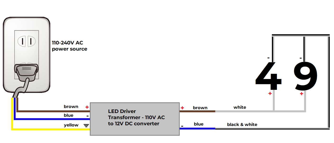
- (Skip this step and move to either the next step or the one after if you purchased either the dusk to dawn light sensor or the timer). Connect all the positive (white)wires of the numbers to the positive (brown) wire on the DC side of LED driver and connect all the negative (black & white) wires of the numbers to the negative (blue) wire on the DC side of the LED driver. Skip the next two steps if you didn't purchase the timer or the light sensor.
- Optional (only if ordered light sensor):
- Connect all the positive wires (white)of the numbers to the positive (red) wire on the OUT side (the side that has two wires) of the light sensor.
- Connect all the negative wires (black & white)of the numbers to the negative (black) wire on the OUT side (the side that has two wires) of the light sensor.
- Connect the positive (red)wire on the IN side (the side that has three wires) of the light sensor to the positive (brown) wire on the DC side of the LED driver.
- Connect the negative (black)wire on the IN side (the side that has three wires) of the light sensor to the negative (blue) wire on the DC side of the LED driver.
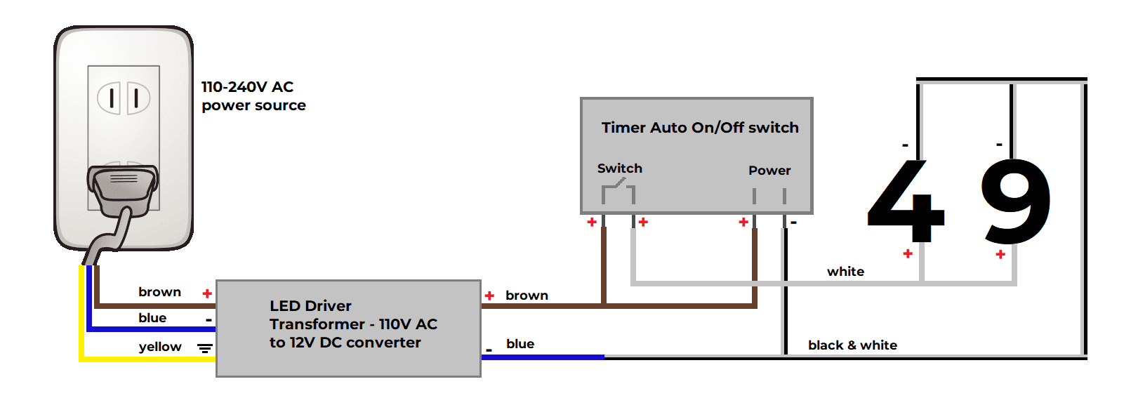
- Optional (only if ordered timer):
- Connect all the positive wires (white)of the numbers to the right side of the switch terminal of the timer.
- Connect all the negative wires (black & white)of the numbers to the negative side of the power terminal on the timer.
- Connect all the negative wires (black & white)of the numbers to negative (blue) wire on the DC side of the LED driver.
- Connect the positive wire (brown)on the DC side of the LED driver to the left side of the switch terminal of the timer.
- Connect the positive wire (brown)on the DC side of the LED driver to the positive side of the power terminal of the timer.
- Connect the positive (brown)wire on the AC side of the LED driver to the positive wire of the AC power source, connect the negative (blue) wire on the AC side of the LED driver to the negative wire of the AC power source, and connect the ground (yellow) wire on the AC side of the LED driver to the ground wire of the AC power source.
Wiring diagram 1 (plug in and without timer or light sensor):
Wiring diagram 2 (plug in and with light sensor):

Wiring diagram 3 (plug in and with timer):
CAUTION:
Installation instructions and wiring diagrams are for reference only. Wiring and installation should be done be a certified electrician after verifying the right connection diagrams, ratings, safety regulations, and electrical code.
The backlit address numbers are 12V DC which means they cannot be connected directly to any AC power source. You will need to connect them to the LED Driver (110V AC to 12V DC) first (make sure to connect them to the correct side of the LED Driver) and then connect the LED driver to the 110V AC power source.
Safety Note: Connecting the backlit address numbers directly to an AC power source (e.g. 110V-240V AC panel, 110V-240V AC outlet, etc.) without the 110V to 12V AC to DC converter (LED Driver) is very dangerous, not safe, and should not be done under any circumstances.